
Wiring diagram questions can be slow. A diagram with twenty components and a stem that says "the thermostat calls for cooling but the compressor does not start" can eat several minutes if you start by staring at the whole drawing. What helps is a tracing routine you apply the same way every time, on paper, from the power source to the load and back. This guide teaches that routine on an original simplified ladder diagram (shown below) and four exercises built on it. It is about reading diagrams for an exam, not about working on energized equipment.
Two kinds of diagrams, one routine
- Pictorial (connection) diagrams show components roughly where they sit in the unit, with wires drawn between terminals. They are good for finding a physical wire and poor for understanding logic.
- Ladder (schematic) diagrams draw two vertical power rails and hang each circuit between them as a horizontal rung: switches and contacts on the left, the load on the right. Every rung is a complete path or it is not, which is exactly the question an exam asks.
Exam questions can use either. If you are given a pictorial diagram and the question is about logic, redraw the relevant rung as a ladder on scratch paper before answering. It costs thirty seconds and prevents most tracing errors.
Read the legend before the wires
Every diagram carries a legend of abbreviations and symbols, and it is the authority for that drawing. Do not assume. In particular:
- Contacts are drawn in their de-energized, "shelf" state. A normally open (NO) contact is drawn open and closes when its coil is energized; a normally closed (NC) contact is drawn closed and opens when its coil is energized. Pressure and temperature switches are drawn in whatever state the legend defines as normal for that switch, and the legend (or the stem) says what condition moves them; do not assume a universal "no pressure" or "room temperature" state.
- Terminal letters, not wire colors, identify circuits. Manufacturer installation guides say it directly: match each labeled wire with the terminal having the same letter, and ignore wire colors. A diagram that labels a low-voltage terminal C is telling you it is the common side of the transformer; it does not matter what color the artist used.
- Dashed lines usually mean field wiring or an optional accessory; solid lines are factory wiring. The legend confirms it.
The five-step tracing routine
- Find the power. Locate the line-voltage source (L1, L2) and the low-voltage source (the transformer secondary, commonly 24 volts). Mark both rails.
- Find the load the question names. Compressor contactor coil, condenser fan motor, indoor blower relay coil, inducer motor, gas valve. Put your finger on it.
- Trace backward from the load to the rail, listing every switch, contact, and safety device in series on the way. Write the list in order. This list is the whole answer to most questions: the load runs only if every item on the list is closed.
- Decide the state of each item for the scenario in the stem. "Thermostat calls for cooling" closes the R-to-Y and R-to-G circuits. "High-pressure switch tripped" opens the high-pressure contact. Mark each item open or closed.
- Answer from the list, within the question's assumptions. In the simplified circuits exam questions use, with the correct voltage on the rails, a working load, and an intact return path, every series item closed means the load is energized, and one item open means it is not, so the open item is the answer to "which component prevents..." questions. Keep the limits in mind: an energized contactor coil closes its contacts, and whether the compressor then runs depends on the line-voltage circuit and the motor itself, which is a separate rung to trace.
Original tracing exercises
These exercises are original practice examples written for this guide, built on the simplified split-system control diagram below. They are not official exam questions, and real equipment diagrams differ. The diagram is an original teaching drawing, not any manufacturer's wiring.
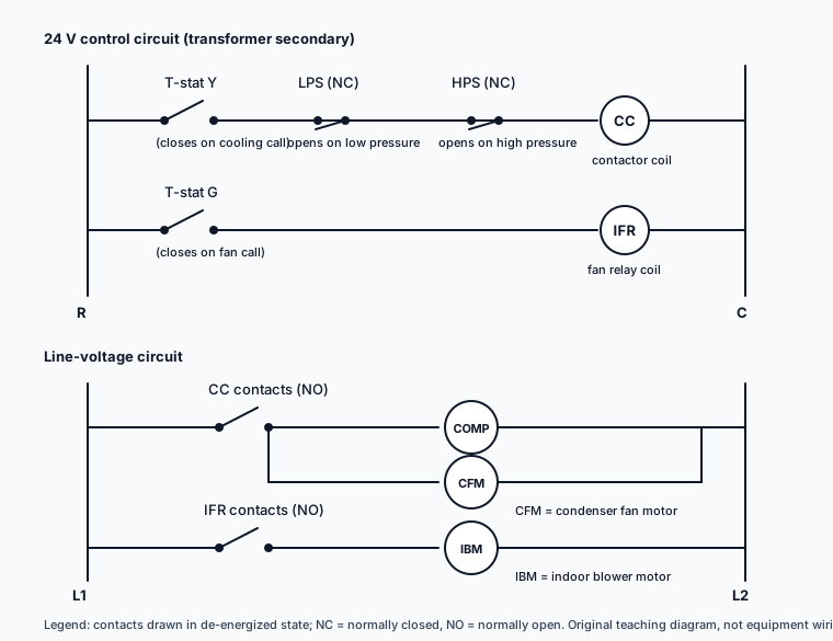
Exercise 1: a normal call for cooling
The diagram shows (Figure 1): a 24-volt transformer secondary with terminals R (hot) and C (common). From R, the thermostat closes R to Y on a call for cooling and R to G for the fan. From Y, a wire runs through a low-pressure switch (drawn NC; the legend says it opens on low pressure), then a high-pressure switch (drawn NC; opens on high pressure), then to the compressor contactor coil CC, and from the coil to C. From G, a wire runs to the indoor fan relay coil IFR, then to C. In the line-voltage circuit, the contactor's NO contacts feed the compressor and the condenser fan motor, and the fan relay's NO contacts feed the indoor blower motor. Assume the transformer, the motors, and the return paths are all good.
Question: The thermostat calls for cooling and both pressure switches are in their normal (closed) state. Which loads energize?
Trace. Contactor coil path: R, thermostat R-Y (closed on a call), low-pressure switch (closed), high-pressure switch (closed), coil, C. Every item closed, so the coil energizes and its NO contacts close; with line voltage present and good motors, the compressor and condenser fan run. Fan relay path: R, thermostat R-G (closed), relay coil, C. The relay energizes, its contacts close, and the indoor blower runs. All three motors run under the stated assumptions.
Exercise 2: the safety in series
Question: Same diagram (Figure 1). The thermostat calls for cooling; the indoor blower runs, but the compressor and condenser fan do not. The contactor coil measures 0 volts across it. Assume exactly one component has failed open, the common (C) side and all wiring are intact, and the coil itself is good. Which choice explains the symptoms? (a) low-pressure switch, (b) transformer, (c) fan relay coil, (d) contactor contacts.
Trace. The blower runs, so the transformer, R, the thermostat's R-G circuit, and the fan relay coil are proven good, which rules out (b) and (c). The contactor coil has no voltage, so something between R and the coil on rung 1 is open. The contactor contacts (d) sit in the line-voltage circuit downstream of the coil; if they were the failed part, the coil would still read 24 volts. That leaves (a), the low-pressure switch, as the only listed component whose open state removes voltage from the coil. Note that the thermostat's Y contact or the high-pressure switch would produce the same symptoms; they are not among the choices, and the single-fault assumption plus the choice list is what makes the answer unique. Without those constraints the symptoms alone would not pick one component.
Exercise 3: NO versus NC
The diagram shows a furnace control circuit (a different drawing from Figure 1) in which the inducer motor starts first and a pressure switch, drawn open and labeled in the legend "closes on inducer airflow," sits in series with the gas valve circuit.
Question: The inducer runs, the pressure switch never closes, and the gas valve never opens. Is the gas valve circuit behaving as designed?
Trace. The legend says this switch is drawn open and closes on inducer airflow, so it must close to complete the gas valve rung. It has not closed, so the rung stays open and the gas valve stays closed. Yes, the circuit is doing its job: the switch is proving inducer airflow before allowing gas. The fault, if there is one, is in whatever should have closed the switch (blocked vent, weak inducer, a failed switch), not in the gas valve. Candidates who assume the switch is normally closed answer this backward.
Exercise 4: the wire-color trap
Question: A diagram labels a thermostat wire "W" and the pictorial shows it drawn in white. A second diagram for a different unit shows a white wire landed on terminal G. Which terminal carries the heat call?
Answer. The terminal marked W on each diagram's legend. Color proves nothing; a manufacturer's own installation guide (Resideo/Honeywell Home, RTH2300/RTH221 quick installation guide) says to match each labeled wire with the terminal having the same letter and to ignore wire colors. That instruction supports this one point about identification; the tracing rules elsewhere in this guide are standard schematic-reading practice, not something that document covers. If both diagrams are in the same question, answer each from its own legend.
Traps to check before you answer
| Trap | How it shows up | Check |
|---|---|---|
| Wrong voltage level | Answer names a line-voltage component for a control-circuit fault | Which rail did you trace from? |
| Contact state assumed | Reading an NO contact as closed because it "should" be on, or assuming a switch's normal state instead of reading it | Legend says how it is drawn; the scenario says what changed |
| Parallel mistaken for series | An open device in a parallel branch does not stop the other branch | Is the device on the load's own path to the rail? |
| Downstream device blamed for upstream symptom | Blaming contactor contacts when the coil has no voltage | Where in the list did the voltage disappear? |
| Coil energized taken as motor running | Answering "compressor runs" from the control rung alone | Trace the line-voltage rung too; the question's assumptions about power and the motor decide |
| Color used as identity | Answer based on a wire color instead of a terminal letter | Read the terminal designation |
Safety note
This routine is for reading diagrams on paper during study and on the exam. Diagnosing real equipment involves energized circuits and manufacturer procedures that are outside the scope of this guide; follow your training, the equipment documentation, and applicable safety rules on the job.
Practice next
The Heating Systems topic walks through the furnace ignition sequence that Exercise 3 is built on. Then take the free HVAC practice test and, on any control or diagram question, write the series list from Step 3 before you choose. The HVAC study guide shows where diagrams fit in the full preparation sequence.
Sources and verification notes
The instruction to identify wires by terminal designation rather than color is from a Resideo/Honeywell Home installation guide (69-2448ES-03); that document supports only that point, not the tracing rules, which are standard schematic-reading practice stated here as the author's method. Contact-state drawing conventions (de-energized state) are conventions; always defer to the legend on the diagram in front of you. Figure 1 and the exercise circuits are original simplified teaching examples, not any manufacturer's wiring and not official exam questions. Exercise 2 is made unique by its stated assumptions and answer choices. This guide covers reading diagrams on paper, not work on energized equipment.
- Resideo/Honeywell Home, RTH2300/RTH221 Quick Installation Guide (match wires by terminal designation, ignore wire colors)Checked September 18, 2026
Written by the ExamsLib editorial team. Practice examples in this guide are original and are not official exam questions. Exam rules change; the candidate bulletin from your licensing authority is the final word. Found an error? Contact us.
